XByWire Prototype
What I Actually Did
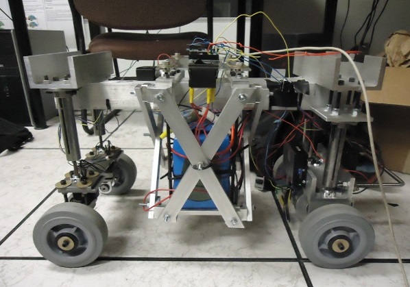
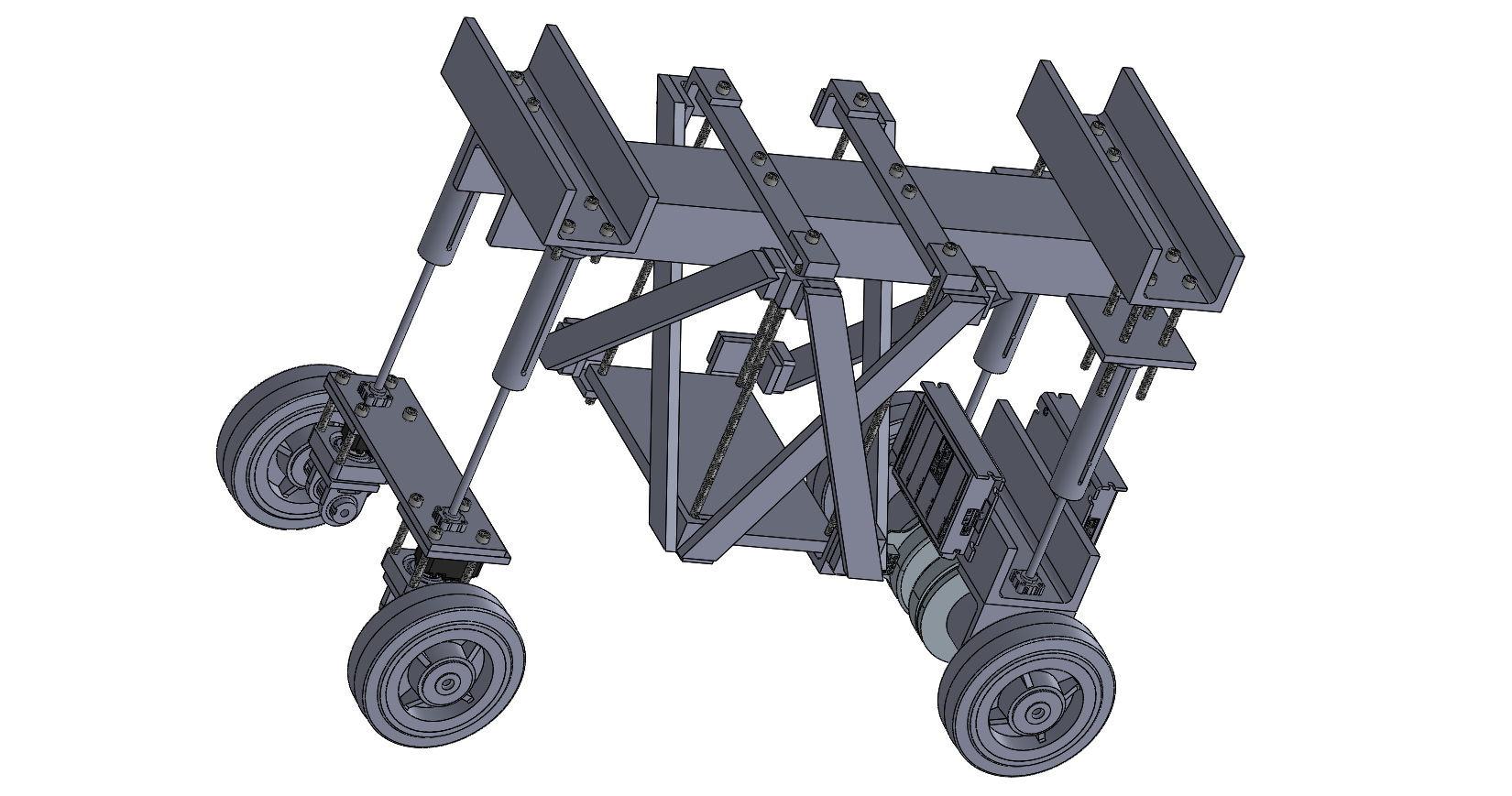
At first, I was a little disheartened because when I saw I had been accepted as an intern I imagined I would be CAD-ing my own creative designs for sci-fi like intelligent robots. Instead, I had just figured out that my job didn't involve mechanical design at all. Little did I know, this was one of the coolest experiences I'd ever have. It was my first time "reverse engineering" an existing technology and trying to figure out what each and every wire on the robot was used for. While there was a thesis paper, there was no documentation on the electrical schematics, and the code was barely commented. Guillaume Sauze also did not provide the CAD files he used to machine parts for the robot, and so I recreated the robot by deconstructing and measuring parts manually with a ruler and caliper.
What I learned
X-by-Wire
The entire concept of X-By-Wire was foreign to me. X-by-Wire means replacing mechanical systems with electrical systems (hence, "X" represents some variable mechanical component which is then replaced "by Wire"). A real world example of this is replacing the mechanical transmission of a car with signal transmission via wire from the steering wheel to the wheels. In the modern day, most commercial cars still rely on mechanical transmissions instead of wire. However, there are various advantages of replacing these mechanical systems with electrical ones. First, mechanical transmissions move in fixed proportion with the steering angle. However, with an electrical system, it is possible to adjust the proportionality constant by the mere change of a signal, whereas a complete disassembly and reassembly would be necessary for a mechanical system. This is useful because changing the proportionality constant could prevent dangerous movements by the driver, thus decreasing accidents. A big reason of why companies haven't transitioned to this technology is because of the fear of electrical systems failing.
Guillaime Sauze's goal was to "build a proof-of-concept complete X-by-wire prototype." Since past research on the benefits of X-b-wire automobiles have been simulation-based, he wanted to create a physical prototype and prove results in the field. He chose to model his prototype off the Toyota Tacoma, so that the track and wheel proportions were the same as this car (just with scaled down values of course).
Serial Communication
While studying the Arduino used to control the prototype, I inevitably stumbled upon the mysterious MOSI, MISO, TX, and RX pins. Nowadays, you grow up being told computers communicate using binary 0's and 1's but you're never really told exactly how that works. During this project, I finally understood what this binary stuff meant-hahaa. I learned the basics of serial communication and the various serial buses I2C, SPI, and UART on the Arduino. Everything started to fall in place for me; it made sense how a series of high/low pulses was the simplest way to send data and why all these buses needed clocks. As a mechanical engineering major, I used to cringe at the thought of anything electrical (something I couldn't visualize before). Now, I've definitely discovered an appreciation and curiosity for electrical engineering.
Motors
One of the first things I noticed on the robot were these two large blocks labeled "ESCON Motor Controller." Examining the wiring, I noticed that these served as some sort of conduit between the motors and microcontroller. What I had stumbled upon was an ESC, or electronic speed conroller. I knew what an ESC was, having worked with it in my RC-car localization project. But since the RC-car was pre-built and I never needed to learn exactly how this ESC worked to work with ROS, I never did. This time around, I did my research.
Personally, I find motors super cool. Especially Brushless DC (BLDC) Motors (which were used in the prototype). They are a direct application of Faraday's Law, which I learned about in the Fall Semester of my freshman year in PHYS 2213. If you don't know, a BLDC is made up of a stator of coils and rotor of magnets. By switching the direction of current in the coils, the stator repels/attracts magnets on the rotor in a sequence such that the rotor rotates. Typically, there are three groups of coils. At any given time, one group is "north", one is "south", and one has no current. That's why there are three wires coming out of a BLDC; each wire controls a different group. The ESC is used to send the sequence of commands to each of these 3 wires necessary to rotate the motor.
Gif from www.renesas.com
RC Filter
Arduino is capable of reading analog signals, but not outputting them. Arduino is capable of outputting a PWM signal, but since PWM is fundamentally just switching rapidly between high and low the motor controller is likely to read an incorrect voltage. When I saw a capacitor connecting the ground pin and VIN Pin (which was connected to an Arduino PWM pin) on the ESCON motor controller, I did my research and found something called a low-pass filter. I realized this low-pass filter was used to smooth out the signal from the PWM pin.
A low-pass filter, as its name suggests, lets low frequency parts of a signal pass through. At first, this confused me. How was any part of the PWM signal going to pass through the filter? A PWM signal is just a high frequency square wave. Intuitively, I expected nothing would pass through. What a low pass filter actually does is pass through the average value of the signal. To understand this concept, it was helpful to think about the concept of beats (which I learned in PHYS 2214: waves). Beats are a result of interference between a high and low frequency wave. What a low pass filter does is effectively remove the high frequency wave which causes ups and downs in the low frequency wave, leaving just the smoothed out low frequency wave. Likewise, the filter removes the rapid ups & downs of the PWM square wave and outputs the average value of the square wave, which is the desired analog output.
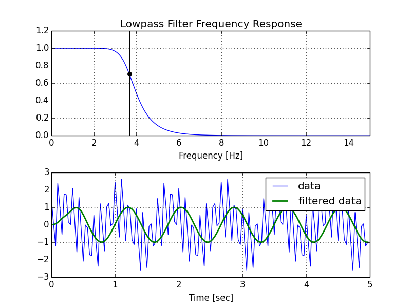
Image from stackoverflow.com
Schematics, Outlines, and Flowcharts
I spent a lot of time understanding the highlighted topics above and other electrical engineering related concepts, but below is some of the work I did specifically for my job.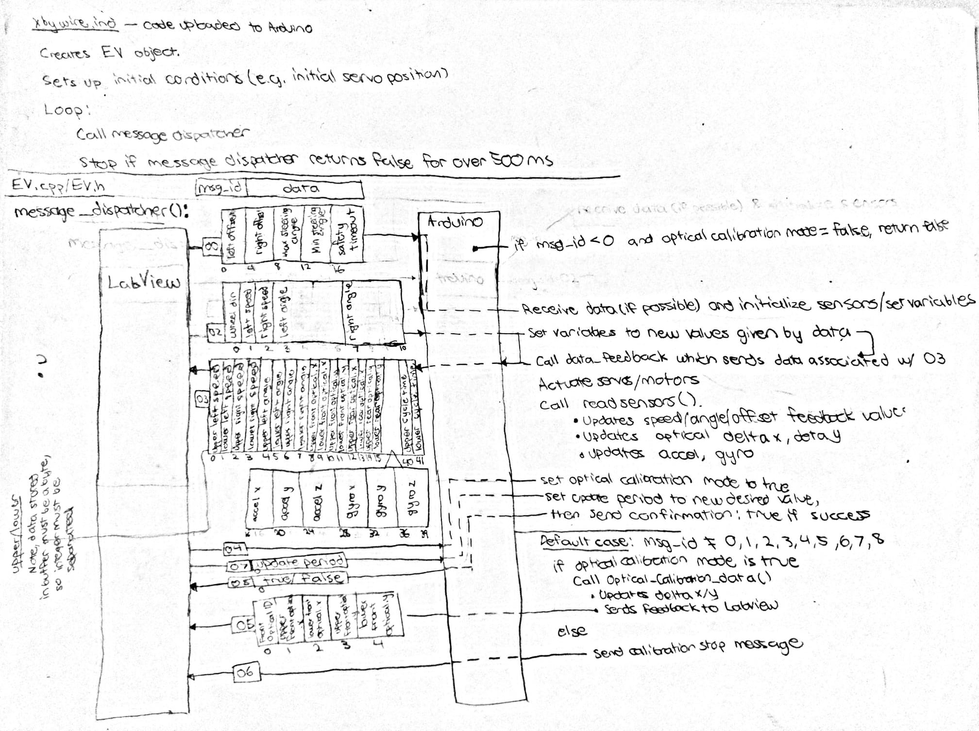
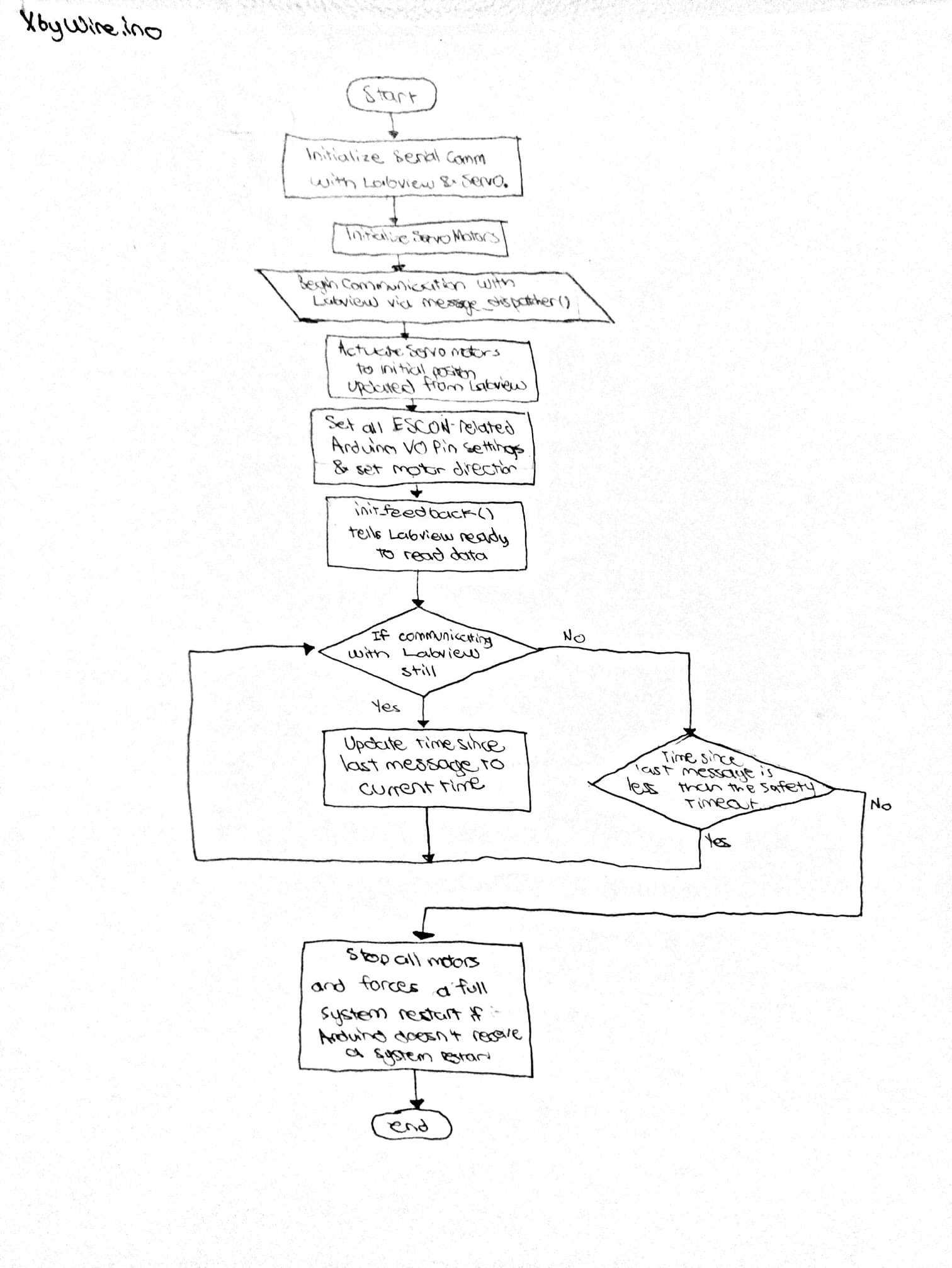
This is an code flowchart I created for xbywire.ino, the main file which is uploaded to Arduino. The code is fairly simple, and is essentially a loop which runs a communication method in the EV class until a signal hasn't been established with Labview user app for over 500ms.
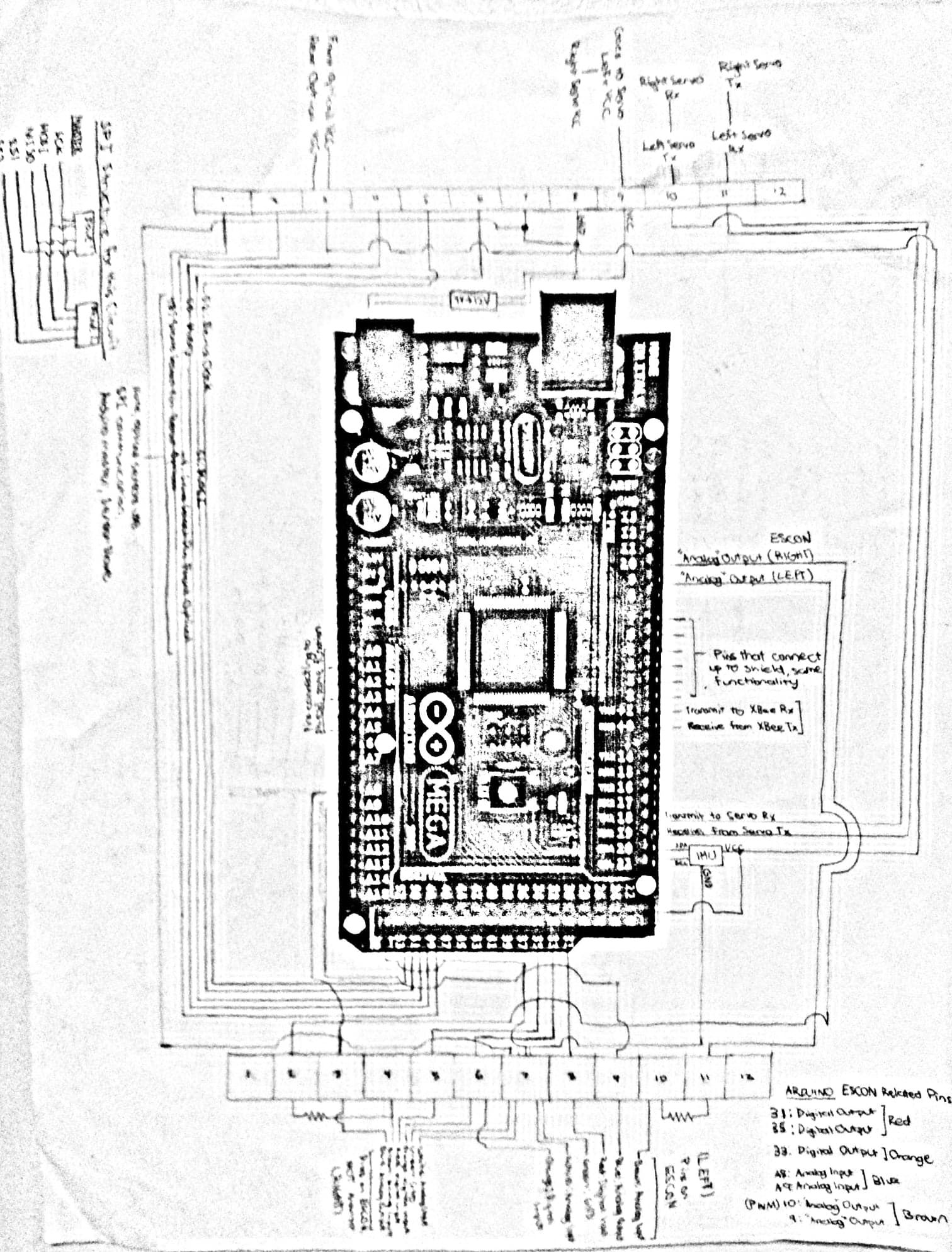
This is a schematic for the I/O pins on the on-board Arduino. This project made full use of the Arduino. Servo communication via the SPI lines, IMU through I2C, and XBee through UART Rx and Tx pins. Many standard digital and PWM I/O pins were used to communicate with the ESCON motor controllers. The numbered blocks above and below the Arduino on the schematic represent the different lines on terminal blocks which were used for wire organization.