IoT Road Temperature Monitoring
Problem
The Roads Team formed as a part of Cornell University’s MAE 4220/ECE 4950 Internet of Things class to attack the problem of monitoring road weather conditions. This problem is particularly relevant to Tompkins County, which experiences adverse weather conditions despite not having an existing road weather monitoring system. The Road Team’s goal is to address this need with an affordable, minimum viable solution with significant impact.
Road weather monitoring is an extremely broad field, and existing systems employed across the United States measure data such as humidity, precipitation depth, pavement temperature, and more. Because this project had to be completed within a single semester, the team chose not to employ an all-encompassing system that collected data for all of such variables. Instead, the team chose to conduct research to determine what data was most crucial to maintaining roads specifically for snowfall and ice. The team ultimately decided to measure subsurface pavement temperature, since this data could be readily used by Tompkins County’s Highway Department to drive anti-icing efforts. The goal of the project is to reduce costs for road weather maintenance by automating and digitalizing the data collection process, which should ultimately lead to increased public road safety, reducing accidents in Tompkins County.
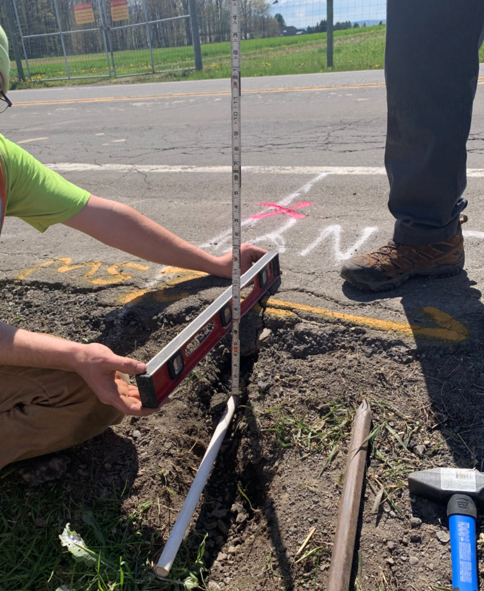
This project was extremely consumer-oriented, in that we were in close contact with community partners who would be directly benefiting from the success of our work. The team made sure to address the needs and requirements of Tompkins County officials. Namely, we worked with Jeffrey Smith, the Highway Director at Tompkins County. Mr. Smith not only advised the team, but also directly assisted the team when acquiring highway permits in order to perform construction on the road during the product installation process. The team also worked closely with Professor David Orr, a senior extension associate with Cornell’s Local Roads Program. Professor Orr has decades of experience with road and highway related research, and provided expert insights that helped guide the design of the team’s final product. Professor Orr also spearheaded the hands-on construction effort portion of the project, allowing the team to install a subsurface thermistor at Game Farm Road. The Roads Team is extremely thankful for the help of these two key community partners.
Brainstorming
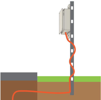
System Architecture
Design Iterations and Waterproofing Testing
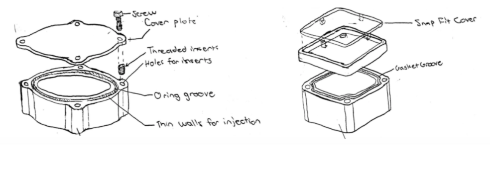
O-Ring Waterproofing Design
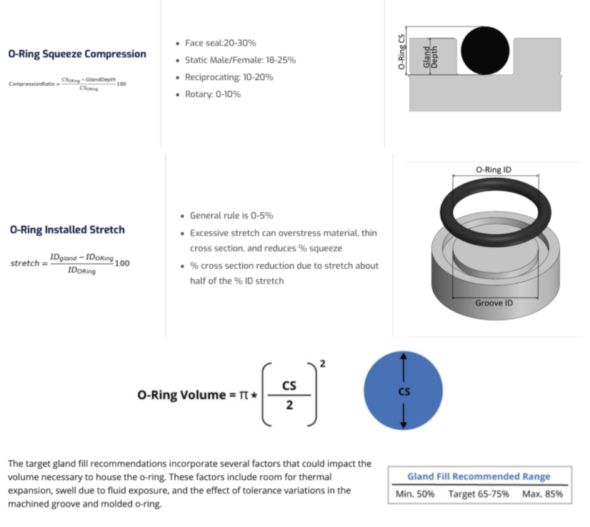
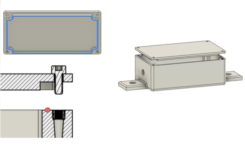
In order to size the o-ring groove, I carried out the sizing calculations shown in the diagram on the left, and subsequently accounted for standard 3D printing tolerances. My calculations affected the inner/outer radii and depth of the groove.
Final Design
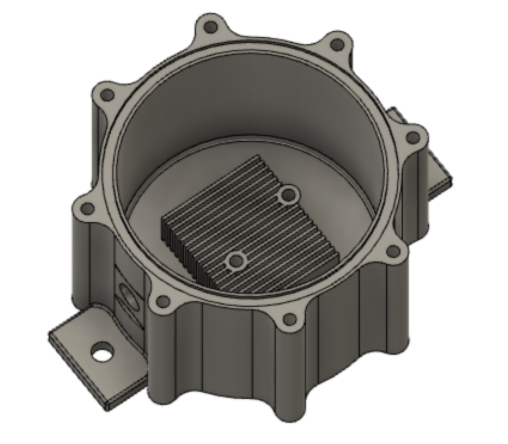
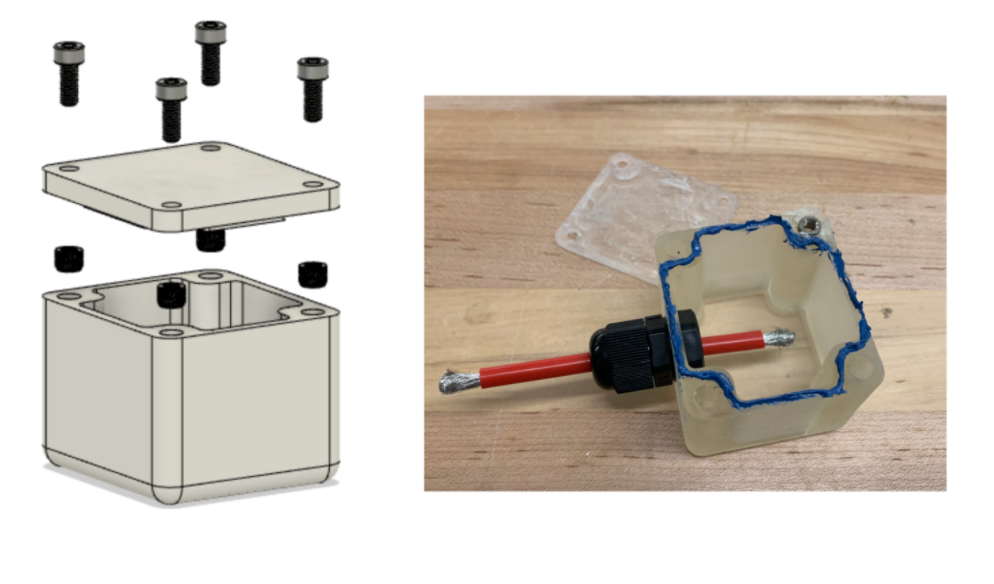
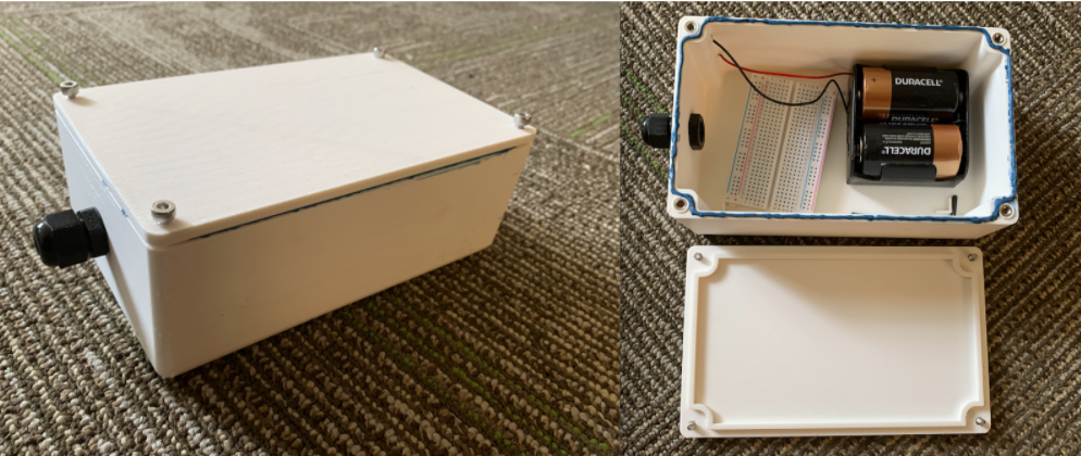
The design to the left shows the my final design for the enclosure. It features a hole for a cable gland that water proofs the outgoing multicore cable connecting to the thermistor probe. It also includes a heatsink with heat insert holes that the battery pack can mount to. Finally, it has a groove and a top cover that the seal the enclosure with an o-ring.
In hindsight, the heatsink attached to the battery case is useless since the enclosure is printed out of ASA plastic, which has a tiny thermal conductivity coefficient of 0.17 W/m-K. In addition, since there are no vents, there isn't enough convection for the fins to be of any use. If I had to redo this design, I would include a scheap heat spreader that would spread heat to every surface within the enclosure in an attempt to take the heat load off of the battery pack. Since we didn't have the budget for a die cast part (or the demand for bulk quantity for that matter), it wouldn't have made sense to make an aluminum enclosure for heat dissipation purposes.
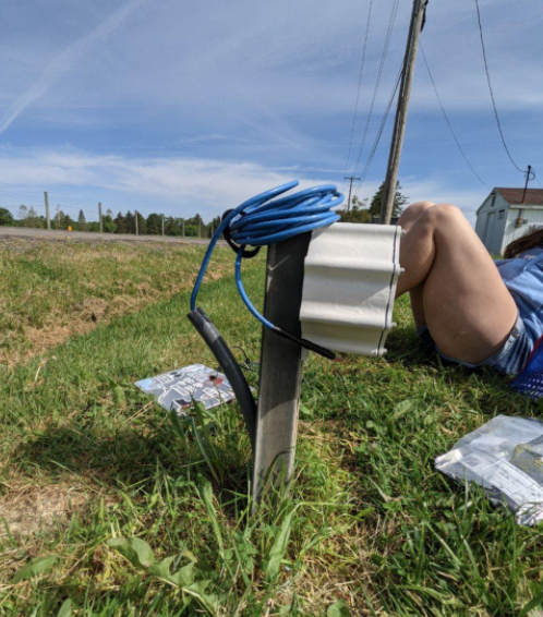
Installation