Water Pump
Brainstorming
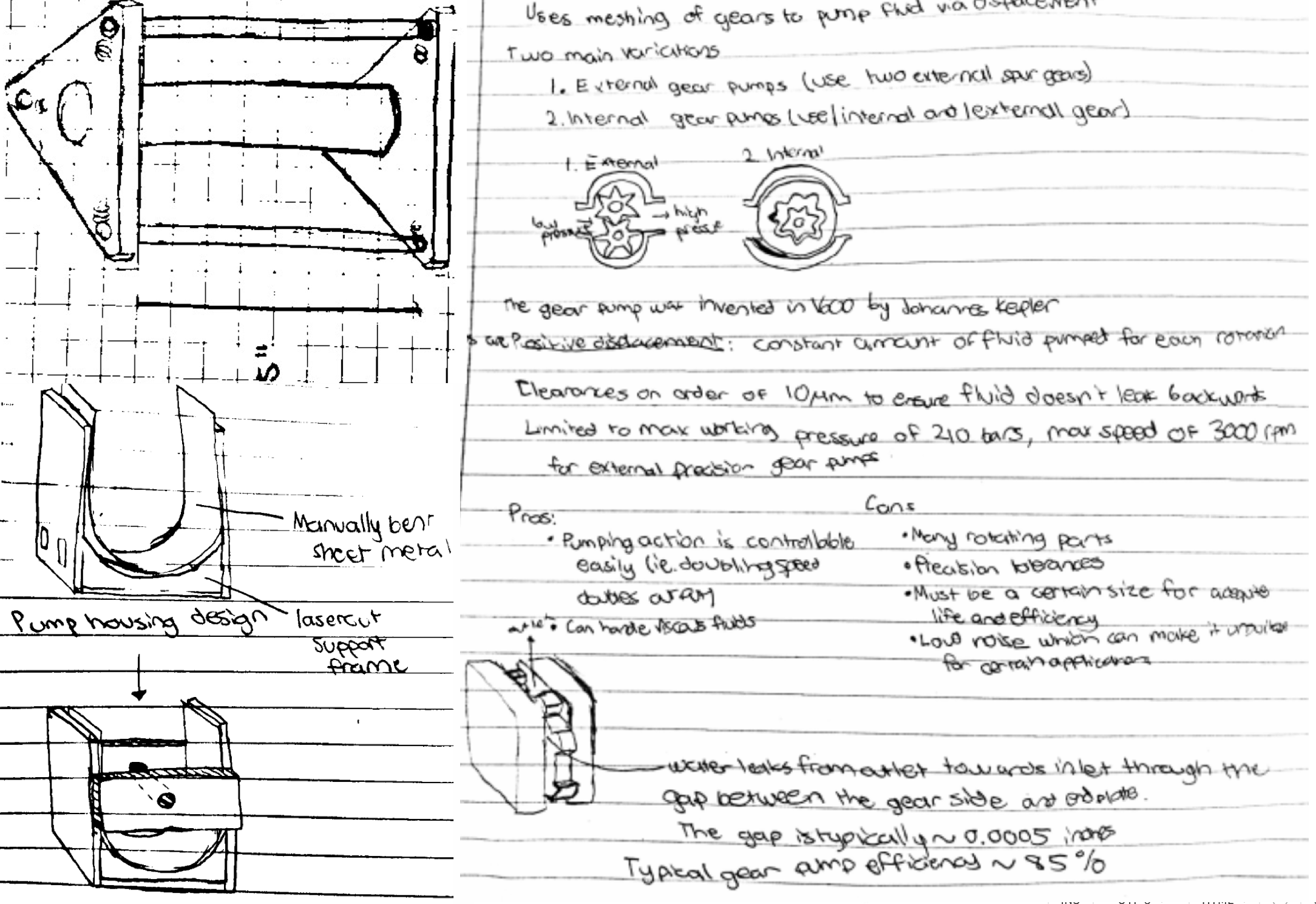
The goal of this project was to build a pump that could pump as much water as possible within a set time frame. My three other teammates and I explored 4 different types of pumps to build—a piston pump, diaphragm pump, peristaltic pump, and gear pump. Ultimately, from a ease of design perspective, we decided to pursue the peristaltic pump design. However, we also wanted to add our own special twist to a standard peristaltic design.
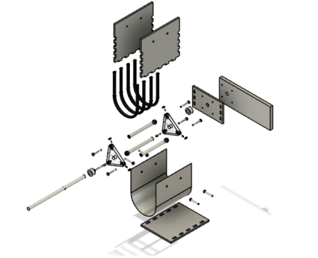
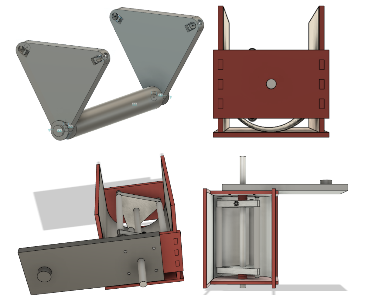
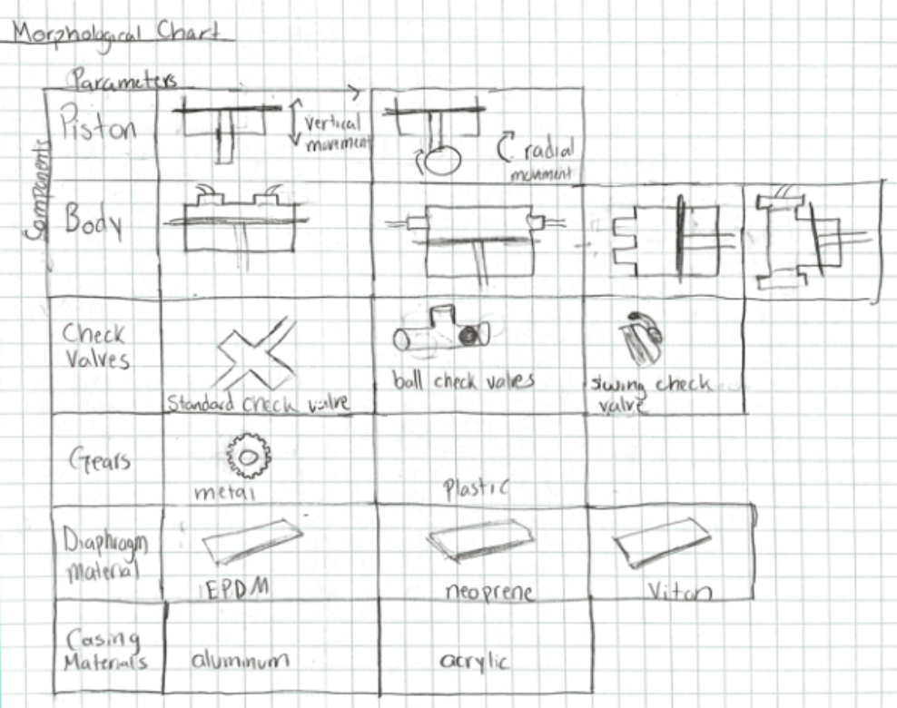
Preliminary Design
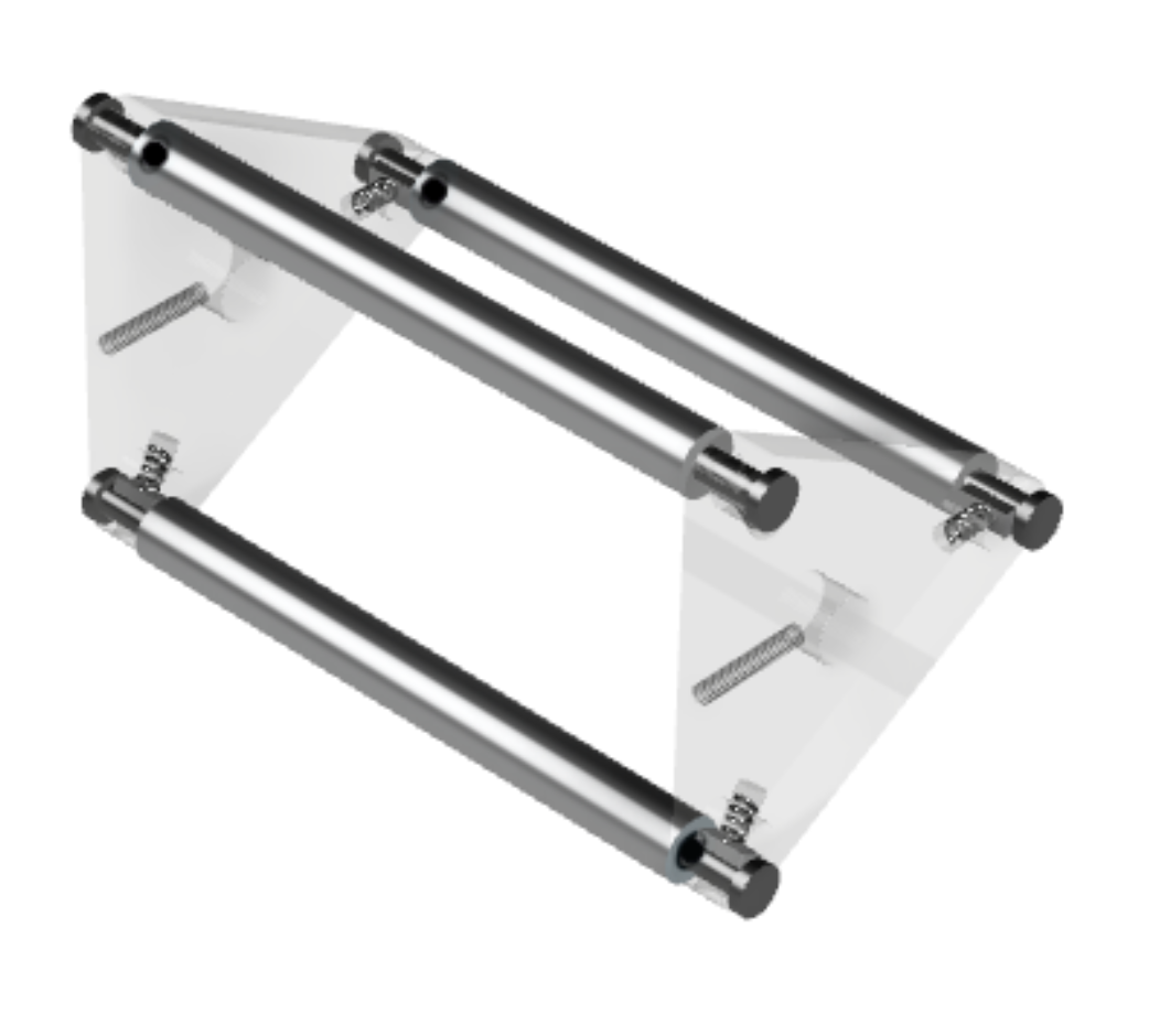
Special Added Feature
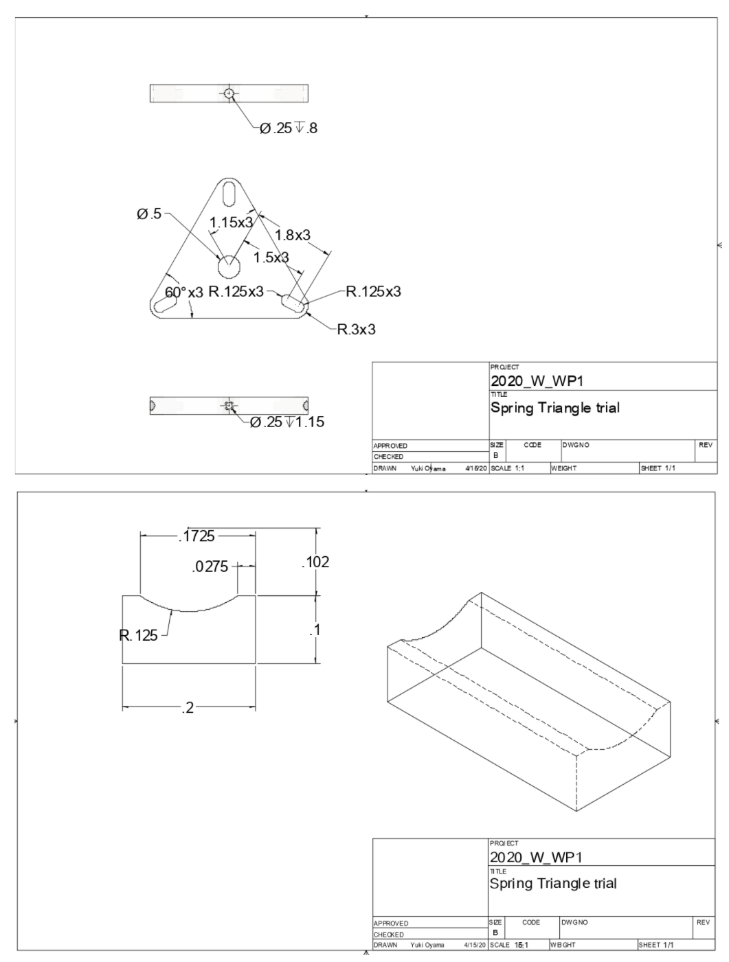
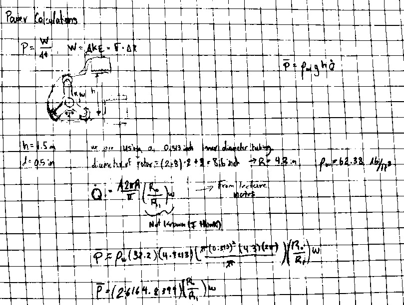
The top drawing shows the triangular rotor with grooves at the vertices that allow the rollers to move axially. Holes are also drilled into the rotor towards the central axis at the vertices to allow for insertion of the springs and the wedge. The bottom drawing shows the wedge that will be welded to the springs. The wedges push against the rollers, providing force to the pump.
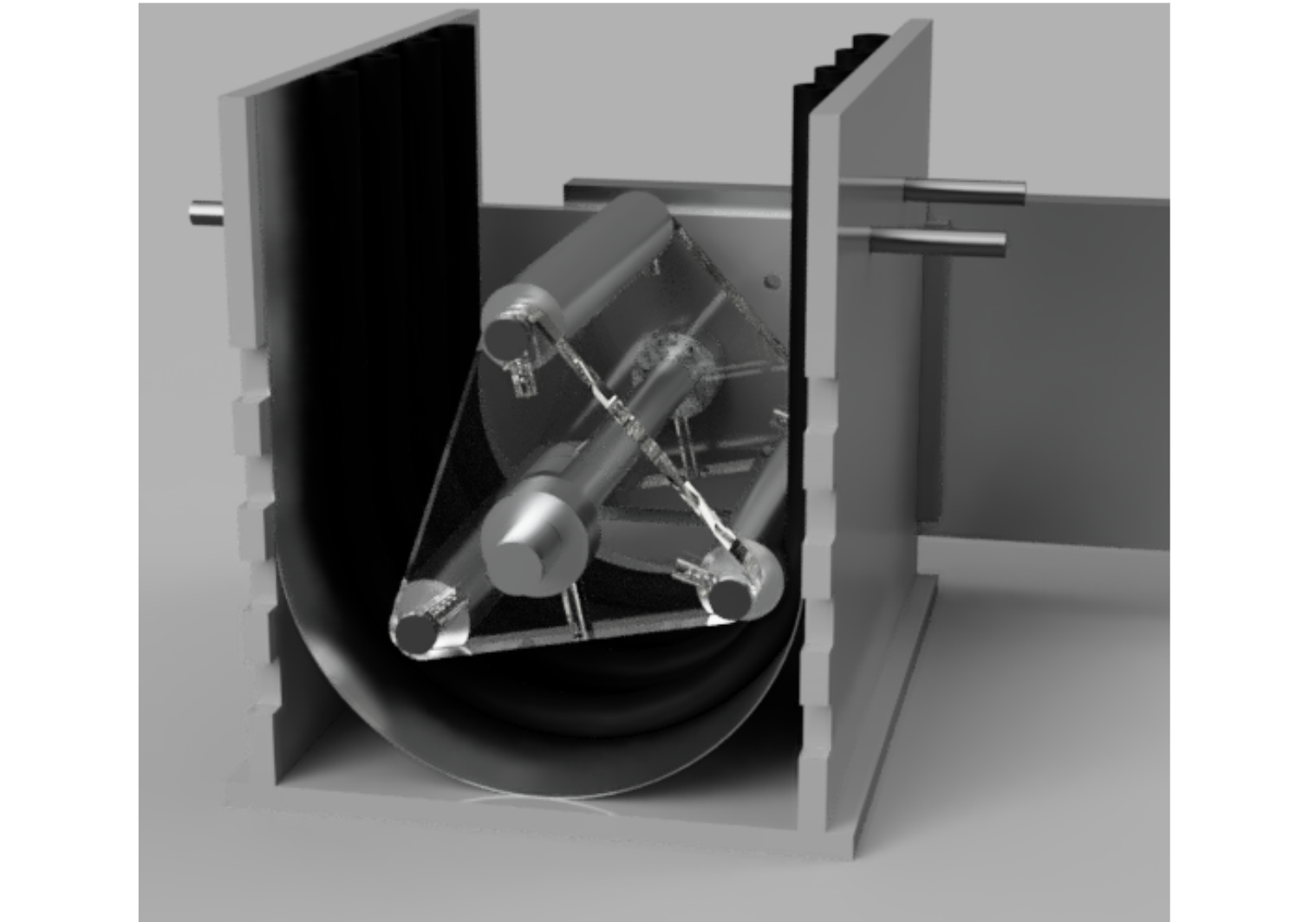
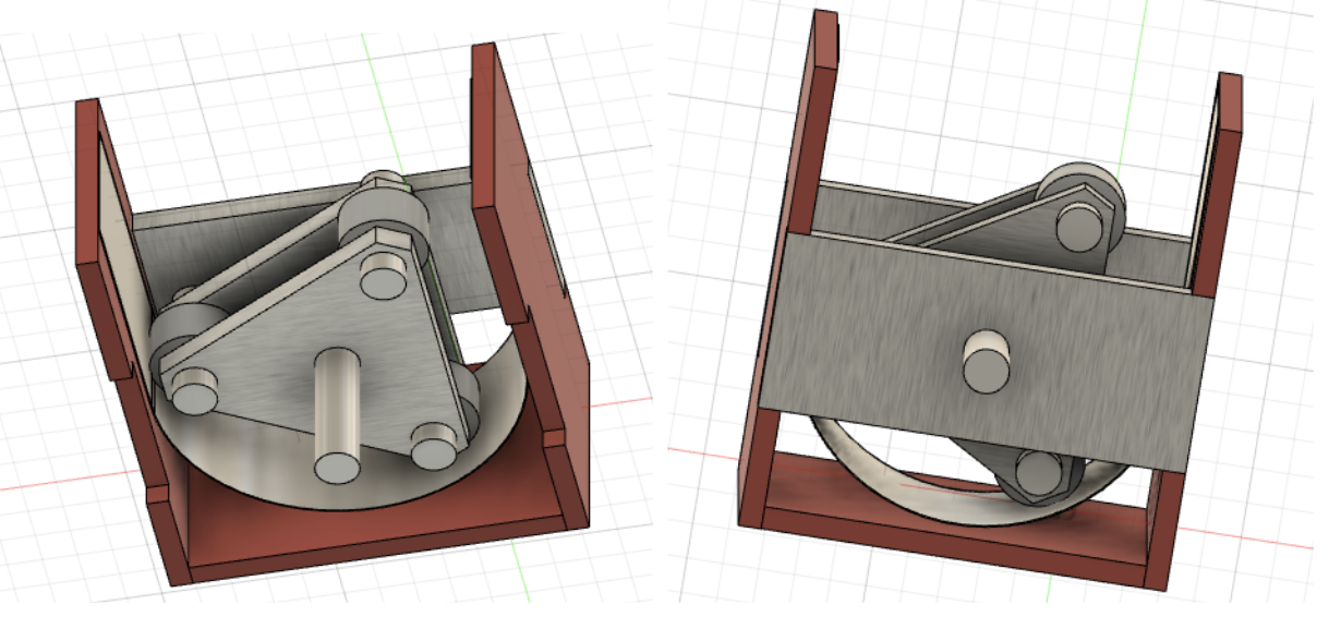
Final Design