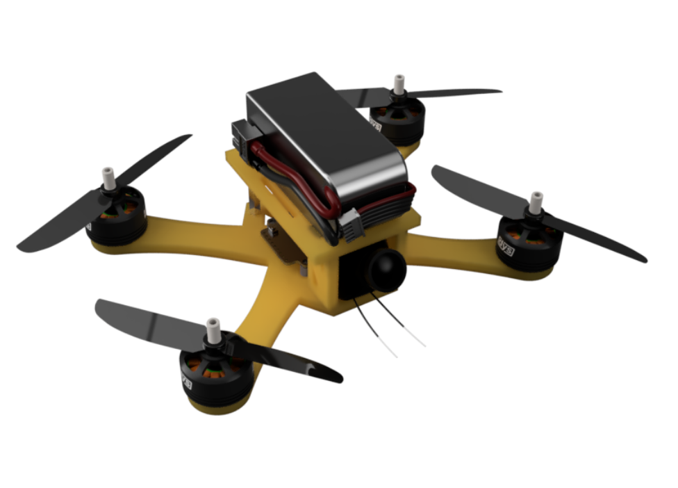
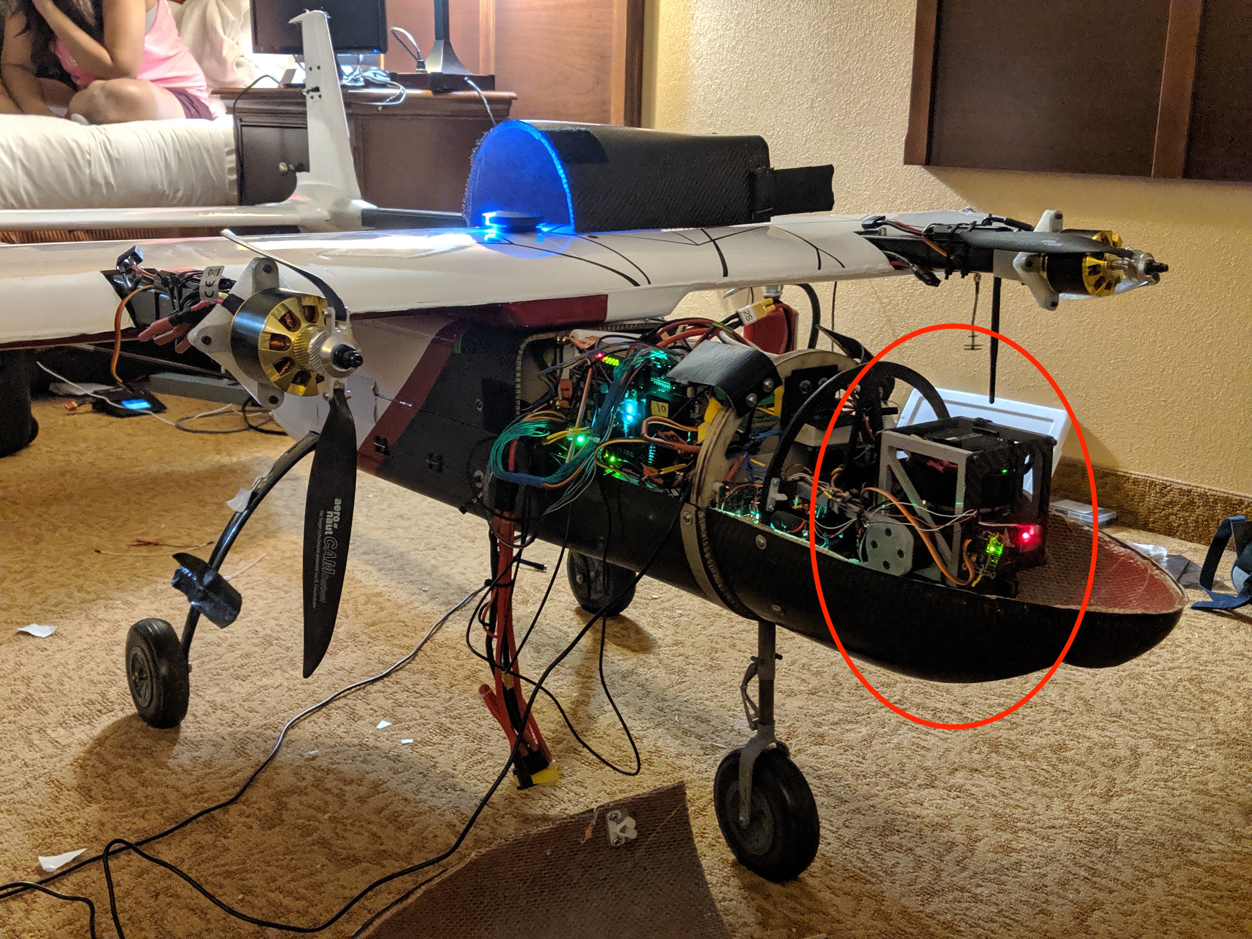
My CUAir Work
Design Objective and Constraints
The software team also wanted the system to be closed loop. Moreover, the system should be able to provide feedback to the controller about the current zoom position.
Lastly the electrical team preferred that I used servo motors as opposed to motors. Servos are useful for a few reasons. From an electrical standpoint, it isn't necessary to include a ESC (electronic speed controller) or H-Bridge as is required by BLDC's and Brushed DC motors respectively. From a software standpoint, it is easy to tell a servo to turn to a specific angle because of the built in encoder or potentiometer within all servos.
Design Rationale
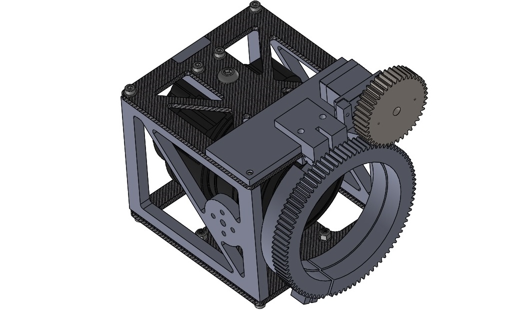
After discussing with a few of my peers, I was convinced that the simplest design would fundamentally consist of two gears— one connected to a servo and another wrapped around the lens.
The first question I had was how I would attach the gear around the lens. Researching commercial zoom pieces online used by filmmakers, I found that many manufacturers made the lens gears out of rubber. The gears were then stretched and attached by pressure/tension. Other manufacturers made wrap-around gears where the gear could be "unravelled" into a line of rubber which could then be wrapped around the lens.
Ultimately, I opted for a design where the gear would act like a clamp that could be tightened with a screw. The reason was that it was easy to rapidly prototype this design using a 3D printer (I couldn't 3D print rubber).

Next, I needed to figure out how to provide positional feedback. While the servos did technically provide angular feedback, I wanted a more foolproof and exact means of feedback. I was worried that the servos could potentially turn too far and damage the camera lens as a result. Therefore, I decided to design a physical limit the camera could turn to.
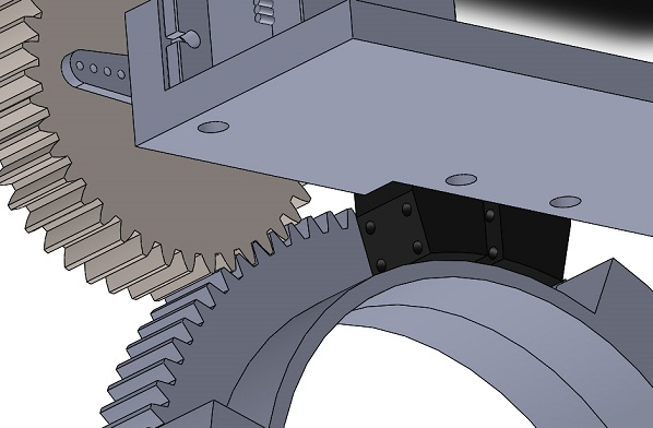
After a few more design iterations, I came up with the design on the left. The black piece shown is the stopper piece which prevents the lens gear (the larger one) from over-zooming. While not shown in the CAD, small push buttons can be inserted into the black stopper piece (the legs of the button fit into the four holes shown).
The push buttons serve as feedback for the servo controller. They send a digital signal indicating whether the camera has zoomed too far, in which case the controller knows to immediately terminate the servo actuation. Notice there is a gap between the two (left and right) stoppers. This gap is to allow the wires to be routed upwards towards the controller board.
Thank You's
Had a lot of help from Theresa Bracht (team lead) and Chrsitine Yuan who were in general a great mentors along the way in my first year on CUAir as a college freshman. Many thanks also to Evan Patrick and Maria Sam on platform software subteam and Joseph Primmer and Adam Weld on the electrical subteam. Extremely cooperative and helpful when I had to make design decisions which affected their work.